メッセージを送信
製品にご興味をお持ちで、詳細を知りたい場合は、メッセージをお送りください。できるだけ早く返信いたします。

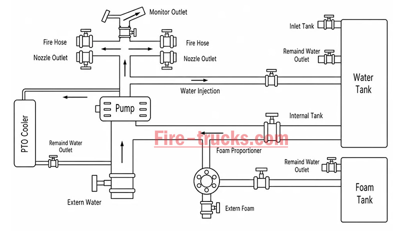
The fire truck PTO (Power Take-Off) is a power transmission device that transfers engine power to the fire pump. When the firefighter activates the PTO, mechanical power from the engine is transmitted through the transmission and PTO to the fire pump — this is the core working principle of how a fire fighting truck PTO system operates — enabling the pump to deliver high-pressure, high-flow water or foam without the need for a separate auxiliary engine.
Modern fire trucks typically use side-mounted PTO or full power PTO systems. These offer stable power output, convenient operation, and low maintenance costs, making them an essential component of the fire truck's firefighting system.
 Work")
PTO (Power Take-Off) is a critical component in the fire truck's power system. It is a gear transmission device installed between the engine and the transmission, designed to "divert" a portion of mechanical power from the vehicle's engine or transmission to the fire pump or other auxiliary equipment, without affecting the vehicle's normal driving capability.
The fire truck engine is originally responsible only for driving the wheels. However, once the fire truck arrives at the fire scene, the wheels no longer need power, while the fire pump requires power to draw and pressurize water. The PTO is the device that accomplishes this "power switch."

Power Take-Off (PTO) literally means "power output device."
On a fire truck, it refers to extracting rotational power from the engine flywheel or transmission gears through gear engagement, and delivering it to the fire pump or other auxiliary equipment.
Its name describes its function:
Engine = Power source
PTO = Power distributor
Fire pump = Power consumption end
Therefore, the PTO is the bridge connecting the "power source" and the "firefighting system."
The core reason fire trucks must be equipped with a PTO is that firefighting operations require continuous, stable, high-power output that cannot rely on the vehicle's driving state.
Main reasons:
1. Provides continuous firefighting power
The fire pump needs to run for extended periods during firefighting operations. The PTO allows the engine to continuously drive the fire pump at idle or fixed RPM, ensuring stable water pressure and flow.
2. Improves power utilization efficiency
Without a PTO, a separate auxiliary engine would be required to drive the fire pump, which would increase:
Cost
Maintenance complexity
Risk of failure
Space occupation
The PTO directly utilizes the vehicle's engine power, improving overall efficiency.
3. Supports multiple firefighting systems
Modern industrial fire trucks may include not only water pumps but also:
Foam systems
Dry powder systems
High-pressure water systems
Remote-controlled fire monitors
Without a PTO, there are only two solutions:
Install a separate engine to drive the pump → increases weight, cost, maintenance points, and occupies space
Keep the pump permanently connected to the transmission → pump stops when vehicle stops, unable to pump water on site
The PTO solves both problems at once:
| Mode | PTO Status | Power Destination | Result |
| Driving mode | Disengaged | All to wheels | Normal driving |
| Firefighting mode | Engaged | All to fire pump | Pumping while stationary |
The PTO is essentially a "power distribution and conversion system" that transforms vehicle driving power into firefighting operational power.
From an engineering perspective, the complete power path is:
Engine → Transmission → PTO → Drive Shaft → Fire Pump → Fire Monitor/Hose System
The PTO's working principle can be summarized in three key stages: power take-off, engagement, and transmission.
The PTO draws power from the engine. Depending on the installation position, the power take-off method differs:
| PTO Type | Installation Position | Power Source | Characteristics |
| Side-mounted PTO | Transmission side | Transmission countershaft gear | Simple structure, lower power (≤50% engine power) |
| Sandwich PTO | Between engine and transmission | Engine flywheel | Full power output, mainstream configuration |
| Split-shaft PTO | Between transmission and driveshaft | Transmission output shaft | High power, allows pumping while driving |
After the driver presses the PTO switch in the cab, the engagement mechanism activates:
| Engagement Method | Working Principle | Common On |
| Electric solenoid control | Electrical signal activates solenoid, pushing shift fork | Mainstream on modern fire trucks |
| Pneumatic control | Compressed air pushes piston, actuating fork | Large fire trucks |
| Manual cable | Mechanical cable directly pulls fork | Older vehicles |
Operation sequence:
Press PTO switch → Solenoid/cylinder actuates → Shift fork pushes sliding gear → Meshes with flywheel or transmission gear → Power connected
After the PTO output shaft begins rotating, power is transmitted through the drive shaft to the fire pump:
PTO output shaft rotates → Drive shaft → Fire pump input shaft → Pump impeller rotates → Water is pressurized and discharged
| Step | Action | Result |
|---|---|---|
| Step 1 | Engine starts, vehicle idling or driving | Engine running, PTO disengaged |
| Step 2 | Arrive at scene, driver presses PTO switch | Driving power disengaged (on some models), PTO gear activated |
| Step 3 | PTO establishes power connection with transmission | Transmission power is diverted to PTO output shaft |
| Step 4 | Drive shaft transmits power to fire pump | Fire pump begins receiving continuous mechanical power |
| Step 5 | Fire pump impeller rotates at high speed | Suction → Pressurization → Delivery to discharge lines → Firefighting |
| Step 6 | System reaches balanced RPM | Stable output, adjustable pressure, flow, and spray pattern |
The fire truck PTO system is a complete power transmission chain, with multiple components working together to transfer engine power to the fire pump. The system can be broken down into six core components:
The engine is the power source of the PTO system and the heart of the entire fire truck.
Function: Generates raw rotational power, driving the flywheel or crankshaft.
Power output: Typically 300–600 HP (depending on chassis model and configuration).
Relationship with PTO: The PTO draws power from the engine flywheel or crankshaft — it is the starting point of power.
Key characteristic: Engine RPM directly affects PTO output speed and the fire pump's water discharge capability. Fire trucks are typically equipped with high-power diesel engines, which not only drive the vehicle but also provide ample power reserve for the fire pump. After PTO engagement, the operator can control pump discharge pressure by adjusting engine RPM.
The transmission is responsible for power delivery and speed matching.
Function: Receives engine power and adjusts speed and torque through different gear combinations.
Relationship with PTO: Side-mounted PTO draws power from internal transmission gears; sandwich PTO is installed at the front of the transmission.
Key characteristic: Transmission gear position does not affect PTO output speed — PTO operates independently of gear selection.
Two power take-off positions:
Transmission side window take-off: PTO mounted on transmission side, drawing power from countershaft or intermediate shaft gears; common on medium-duty fire trucks.
Transmission rear-end take-off (sandwich): PTO installed between engine and transmission, drawing power directly from the flywheel, enabling full power output.
The PTO is the core of the entire system, responsible for "extracting" power from the engine and delivering it to the fire pump.
Function: Extracts power from the engine or transmission and converts it to the speed and torque suitable for the fire pump.
Installation position: Transmission side (side-mounted) or between engine and transmission (sandwich).
Key characteristic: Determines power transmission efficiency, speed matching, and operational convenience.
The drive shaft is the "power bridge" connecting the PTO and the fire pump.
Function: Transmits rotational power from the PTO output shaft to the fire pump input.
Structure: Typically consists of a metal shaft tube, universal joints, and splined connections.
Key characteristic: Must be precisely aligned to avoid vibration; universal joints allow angular compensation.
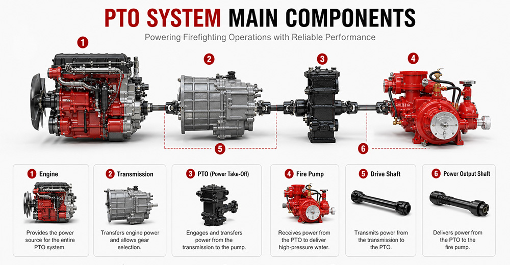
The fire pump is the final load of the PTO system, responsible for converting mechanical energy into water pressure energy.
Function: Receives rotational power from the PTO, drives the impeller to rotate, draws water in, and discharges it under high pressure.
Type: Centrifugal pump (single-stage, two-stage, or multi-stage).
Typical flow rate: 20 L/s – 180 L/s (1,200 – 6,000 L/min).
Typical pressure: 1.0 – 2.5 MPa (10 – 25 bar).
The PTO control system is the "command center" between the driver and the PTO system, responsible for engagement, disengagement, safety protection, and status indication.
Function: Controls PTO engagement and disengagement, monitors system status, and provides safety protection.
Operating location: Cab interior (primary control) and pump panel (auxiliary control).
Control methods: Manual cable, electric solenoid, pneumatic.
Specific control functions:
(1) PTO Engagement Control
The operator presses the PTO switch (electric solenoid/pneumatic) or pulls the lever (manual) in the cab. The control system sends a signal to engage the PTO's internal gears with the power source. After successful engagement is confirmed, an indicator light illuminates, allowing the operator to increase engine RPM.
(2) PTO Disengagement Control
The operator presses the switch again or resets the lever. The control system cuts the signal, and the PTO gears disengage. After disengagement is confirmed, the indicator light turns off.
| PTO Type | Installation Position | Power Source | Power Output | Typical Application |
| Sandwich PTO | Between engine and transmission | Engine flywheel | Full power (≥90%) | Fire pumpers, aerial trucks |
| Split-shaft PTO | Middle of chassis driveshaft | Transmission output shaft | Full power | Large vacuum trucks, airport fire trucks |
| Side-mounted PTO | Transmission side | Transmission gears | Partial power (lower) | Sprinkler trucks, small vacuum trucks |
Sandwich PTO
Advantages: Full power output (≥90%), supports "pumping while driving" (dual-function), high transmission efficiency, easy lubrication.
Disadvantages: Higher cost, complex installation, requires modification to the engine-transmission connection.
Split-shaft PTO
Advantages: Full power output, no additional space required, high reliability, good dynamic balance, can replace auxiliary engine to drive large pumps.
Disadvantages: Requires cutting the original driveshaft, installation position selection must consider driveshaft angle and length compensation.
Side-mounted PTO
Advantages: Low cost, simple installation, can draw power directly from the transmission side.
Disadvantages: Only partial power available, lower output torque, cannot drive high-power fire pumps, mainly used for low-speed, low-power equipment.
 for Fire Trucks")
The process follows a clear mechanical transmission chain:
Engine → PTO → Drive Shaft → Fire Pump → Impeller Rotation → Suction → Pressurization → Fire Monitor
| Factor | Role |
|---|---|
| Centrifugal pump characteristic | When impeller speed is constant, discharge pressure remains naturally stable |
| PTO rigid connection | No slippage or power loss, ensuring continuous stable power input |
| Pressure governor | Automatically detects flow changes and adjusts engine RPM to maintain set pressure |
| Relief valve | Automatically bypasses when pressure exceeds limit, preventing equipment damage |
① Pump speed is determined by engine RPM
Fire pump impeller speed = Engine RPM × PTO ratio. The PTO ratio is fixed (e.g., 1.75:1), so pump speed changes directly with engine RPM.
Calculation formula:
Engine RPM × PTO ratio = Pump speed (RPM)
② Physical relationship between pressure and speed
The pressure generated by a centrifugal pump is proportional to the square of the impeller speed. This physical law means that small changes in RPM cause significant pressure fluctuations.
Speed increases → Centrifugal force increases → Discharge pressure rises
Speed decreases → Centrifugal force decreases → Discharge pressure drops

1. PTO will not engage
Possible causes: Low air pressure (pneumatic type), faulty solenoid, damaged or stuck cable, interlock conditions not met (parking brake not applied, transmission not in neutral).
Solutions: Check air system pressure (must be ≥0.6 MPa); test solenoid; inspect cable; confirm parking brake is applied and transmission is in neutral.
2. PTO engages but pump does not work
Possible causes: PTO clutch failure, broken drive shaft or worn splines, damaged internal gears.
Solutions: Check PTO clutch engagement; inspect drive shaft for breakage or loose connections; disassemble and inspect internal gears.
3. PTO unusual noise
Possible causes: Poor gear meshing or wear, worn bearings, insufficient or degraded lubrication, PTO not fully disengaged.
Solutions: Check gear clearance and tooth wear; inspect bearings; replace with qualified lubricant; confirm PTO is fully disengaged.
4. PTO oil leakage
Possible causes: Worn or deteriorated seals, cracked housing, loose mounting bolts.
Solutions: Replace seals (O-rings, oil seals); inspect housing for cracks; tighten mounting bolts.
5. PTO overheating
Possible causes: Prolonged high-load operation, insufficient or degraded lubricating oil, cooling system failure.
Solutions: Reduce load or shut down for cooling; replace with qualified lubricant; inspect cooling lines.
6. PTO insufficient power
Possible causes: Improper PTO ratio selection, engine RPM set too low, clutch slippage.
Solutions: Confirm PTO ratio matches the fire pump; increase engine RPM to rated operating range; inspect clutch for slippage.
Q1. What does PTO stand for on a fire truck?
PTO stands for Power Take-Off. It is a mechanical system that transfers engine power from the truck's transmission to the fire pump. In simple terms, PTO allows the fire truck's engine to power the pumping system so it can deliver high-pressure water or foam for firefighting operations without needing a separate engine. It is a critical component in industrial and municipal fire trucks.
Q2. Why do fire trucks need a PTO?
Fire trucks need a PTO because it enables the vehicle's main engine to drive the fire pump efficiently. Without a PTO, the fire pump would require a separate engine, which increases cost, weight, and maintenance complexity. PTO systems provide a compact, reliable, and fuel-efficient way to ensure continuous water or foam supply during firefighting operations.
Q3. Can a fire truck operate without a PTO?
Most modern fire trucks cannot operate their pumping system without a PTO because the PTO is responsible for transferring engine power to the fire pump. However, some specialized fire vehicles may use an independent auxiliary engine to drive the pump. These designs are less common due to higher cost, increased maintenance, and lower efficiency compared to PTO-based systems.
Q4. What is the difference between PTO and a fire pump?
The PTO is a power transmission device, while the fire pump is a water or foam pumping system. The PTO delivers mechanical power from the engine to the pump, and the fire pump converts that power into hydraulic pressure to move water or foam. In short, PTO is the "power source connector," and the fire pump is the "firefighting output device."
Q5. How much power can a fire truck PTO provide?
The power output of a fire truck PTO depends on the vehicle design and transmission system. Typically, PTO systems can provide between 50 kW to over 300 kW of mechanical power. Heavy-duty industrial and airport fire trucks often use high-capacity PTO systems capable of supporting large-flow fire pumps and continuous high-pressure operations.
Q6. What are the different types of fire truck PTOs?
There are several types of fire truck PTO systems, including side-mounted PTO, rear-mounted PTO, split shaft PTO, and full power PTO. Side-mounted PTO is commonly used in standard fire trucks, while split shaft and full power PTO systems are used in industrial and airport fire trucks where higher power output and continuous operation are required.
Q7. How do you maintain a fire truck PTO?
PTO maintenance includes regular inspection of lubrication oil levels, checking for leaks, tightening mounting bolts, and ensuring proper alignment of the drive shaft. Operators should also test engagement and disengagement functions regularly. Preventive maintenance is essential to avoid overheating, mechanical wear, and unexpected failure during emergency operations.
Q8. What causes a fire truck PTO to fail?
Common causes of PTO failure include insufficient lubrication, worn gears, misalignment of the drive shaft, overheating, and improper operation by the driver. Electrical or hydraulic control system failures can also prevent PTO engagement. Regular maintenance and correct operating procedures significantly reduce the risk of PTO failure.
Q9. Which PTO is best for industrial fire trucks?
For industrial fire trucks, the best option is usually a split shaft PTO or full power PTO system. These systems can handle high power output, continuous operation, and large-capacity fire pumps. They are widely used in petrochemical plants, refineries, airports, and large industrial facilities where reliable and long-duration firefighting performance is required.
Q10. What should buyers consider when choosing a fire truck PTO?
Buyers should consider engine power compatibility, required fire pump flow rate, vehicle type, and working environment. It is also important to evaluate PTO durability, cooling performance, maintenance accessibility, and compatibility with the chassis. For export projects, compliance with international standards and local regulations should also be taken into account to ensure approval and operational reliability.
PTO (Power Take-Off) is the core system that transfers engine power to the fire pump — it determines whether the entire firefighting system can operate properly.
The fire truck power chain is: Engine → Transmission → PTO → Drive Shaft → Fire Pump → Fire Monitor. Any weak link in this chain affects final firefighting performance.
The primary function of the PTO is to provide stable, continuous mechanical power output, enabling the fire truck to deliver efficient water or foam supply without requiring a separate engine.
Different PTO types (Side-mounted, Rear-mounted, Split shaft, Full power) are suited to different fire truck classes. Industrial fire trucks typically prioritize high-power PTO systems.
PTO performance must match the fire pump flow rate and vehicle chassis, otherwise issues such as insufficient power, unstable pressure, or system overload may occur.
Regular PTO system maintenance (lubrication, tightening, alignment inspection) is key to ensuring reliable fire truck operation, especially in high-intensity industrial applications.
When purchasing industrial fire trucks, buyers should not focus solely on price. PTO power, stability, compatibility, and after-sales support are equally critical factors to evaluate.
For high-risk scenarios such as petrochemical plants, airports, and large industrial parks, Full Power PTO or Split Shaft PTO systems are recommended to ensure continuous operational capability.


次の情報に興味があるかもしれません
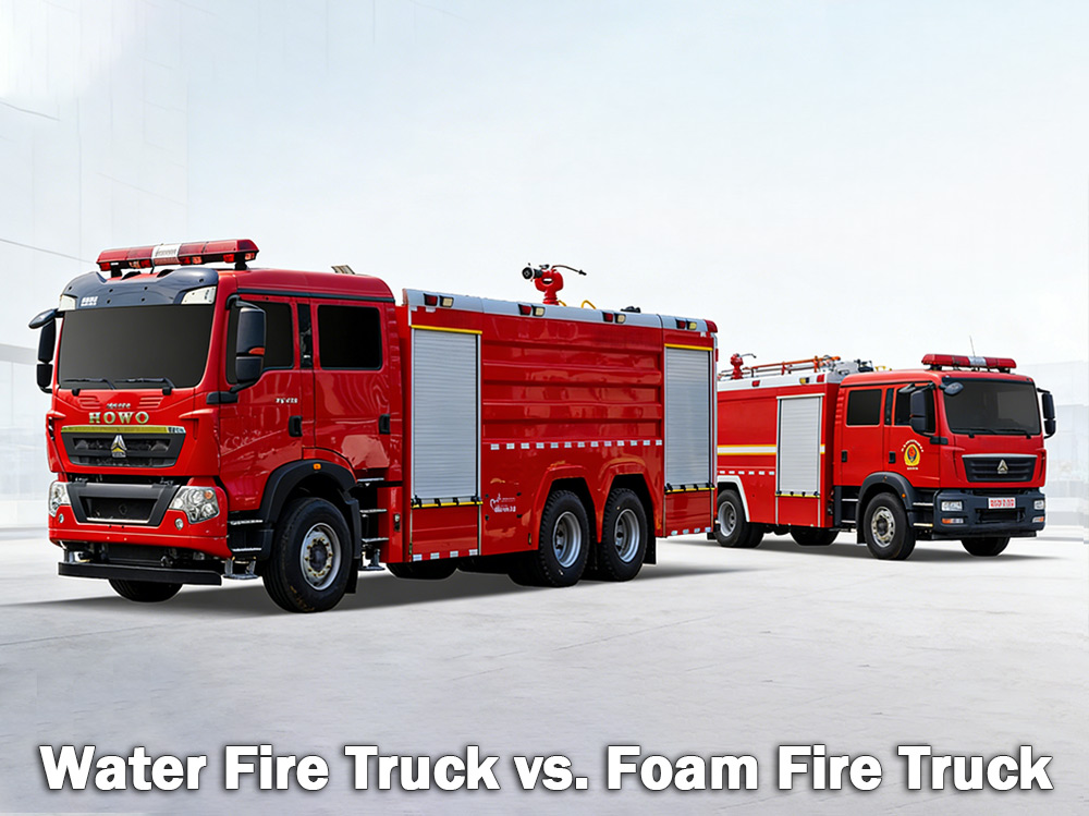
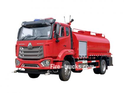
水消防車 通常の火災は、木材、紙、布などの火災に対応します。泡消火車は、ガソリンや油などの可燃性液体火災に対応します。どちらが適切かは、発生する危険の種類によって異なります。 A 水消防車 大型の水タンクを搭載し、高圧ポンプでホースや放水銃を通して水を供給します。世界中の自治体消防署や工場で最も一般的に使用されている消防車です。 A 泡消火車 一方、は消火用泡を運搬・散布するために特別に設計されています。可燃性液体、化学物質、燃料火災など、水だけでは効果的に消火できない場合は、泡の方が適しています。泡は火の上に覆いかぶさるようにして酸素を遮断し、再燃を防ぐことで消火します。 I. 水消防車とは? 放水消防車とは、その名の通り、大型の水タンク、強力なポンプ、そして火災現場に水を供給するためのホースや放水銃を備えた車両です。水タンクの容量は通常500~3,000ガロン(約2,000~12,000リットル)です。ポンプはタンク内、または消火栓、湖、池などの外部水源から水を汲み上げ、高圧でホースを通して送り出します。 水消防車が最も効果を発揮する場所: 水消防車は、 A級火災 これには、通常の可燃物が含まれます。 木材 紙と段ボール 布地と生地 ゴムとプラスチック 草、低木、森林の材料 火災が家屋、倉庫、または畑で燃える物質に関わるものであれば、通常は水で消火できます。 水の制約: 水には大きな弱点が一つあります。ガソリン、油、化学薬品などの燃えている液体に水をかけると、水はこれらの燃料よりも重いため沈んでしまいます。燃料は水面に浮かび、燃え続けます。場合によっては、水によって火がより広い範囲に広がることもあります。そのため、可燃性液体火災に対しては、水だけでは効果的ではありません。 消防車用消火ポンプの仕様: 水消防車 火災監視装置 仕様: II. 泡消火車とは? 泡消火車は、消火用泡を運搬・散布するために設計された特殊車両です。水用タンクと泡消火剤用タンクの2つのタンクを搭載しています。泡混合システムは、通常、泡消火剤と水の割合を1%、3%、または6%に調整します。この混合液は泡ノズルを通過し、そこで空気が加えられることで、膨張した安定した泡の層が形成されます。 発泡体の仕組み: 泡は燃焼している液体または物質の上に層を形成します。この層は次のような効果を発揮します。 火への酸素供給を遮断する 燃料表面を冷却する 可燃性蒸気の漏洩を防ぎます 火が再び燃え上がるのを防ぐ 泡消火車が最も効果を発揮する場所: 泡消火車は、 B級火災 可燃性および引火性液体に関わるもの: ガソリンとディーゼル ジェット燃料と灯油 油とグリース アルコールとエタノール 工業用化学薬品 泡消火剤は、積み重ねられた商品のある倉庫やタイヤ保管施設での火災など、水だけでは消火が困難な特定のA級火災にも効果的です。 一般的な用途: 応用 発泡体が機能する理由 空港 ジェット燃料火災には泡消火剤が必要であり、水では効果がない。 石油精製所 現場には大量の可燃性液体が存在する 化学工場 水に浮いて燃え続ける化学物質 燃料貯蔵施設 ガソリンとディーゼル燃料のタンクが至る所にある 鉱山および海洋プラットフォーム 危険物質が存在する高リスク地域 石油化学施設 泡が再燃を防ぎ、蒸気を制御します 泡の混合プロセス: 産業用消火活動で使用される泡は、泡消火剤原液を水と混合し、さらに混合液に空気を混ぜて安定した泡を形成することで作られます。この泡は、ホース、ノズル、または泡消火装置を通して噴射され、正確な範囲に散布されます。 発泡体の限界: 泡消火車は購入費用が高額です。追加のタンクと混合システムが必要となり、消火剤原液自体も継続的な費用がかかります。また、システムが正しく混合されていることを確認するために定期的な検査も必要です。施設で液体燃料火災が発生することが稀な場合は、追加費用に見合うだけのメリットがないかもしれません。 泡消火ポンプ搭載型消防車の仕様: 泡消火車 火災監視装置 仕様: 泡消火車 フォームプロポーショナー 仕様: III.水消防車と泡消防車の主な違い › 消火方法:給水車は水を使って冷却・消火し、泡消火車は泡消火剤を噴射して窒息させ、酸素を遮断します。 › 主な火災の種類:給水車はA類火災(木材、紙、布、プラスチック)に対応し、泡消火車はB類火災(ガソリン、油、化学薬品、ジェット燃料)に対応します。 › タンク構成:給水車は給水タンクのみを搭載。泡消火車は給水タンクと消火剤タンクの両方を搭載。 › 追加システム:給水車にはなし。泡消火車には泡消火剤混合システムあり。 › スピードと効率:給水車は信頼性が高いが、より多くの水が必要になる場合がある。泡消火車は燃料火災の消火速度が速い。 › 購入費用:散水車の方が安く、泡消火車の方が高い。 › 消火方法:給水車は水を使って冷却・消火し、泡消火車は泡消火剤を噴射して窒息させ、酸素を遮断します。 › 主な火災の種類:給水車はA類火災(木材、紙、布、プラスチック)に対応し、泡消火車はB類火災(ガソリン、油、化学薬品、ジェット燃料)に対応します。 › タンク構成:給水車は給水タンクのみを搭載。泡消火車は給水タンクと消火剤タンクの両方を搭載。 › 追加システム:給水車にはなし。泡消火車には泡消火剤混合システムあり。 › スピードと効率:給水車は信頼性が高いが、より多くの水が必要になる場合がある。泡消火車は燃料火災の消火速度が速い。 › 購入費用:散水車の方が安く、泡消火車の方が高い。 IV.ニーズに合った消防車の選び方 水消防車と泡消防車のどちらを選ぶかを決める際には、施設の具体的な火災リスクを考慮してください。 水消防車を選ぶべき場合: 主な火災リスクは、一般的な可燃物に関連するものです。 建物、倉庫、オフィス、学校、住宅は、A級火災の原因となる物質で燃える。水は完璧な消火剤となる。 あなたは一般製造業、鉱業、または建設業に従事しています。 これらの施設には、迅速かつ容易にアクセスできる消防設備が必要です。給水車は信頼性が高く、費用対効果にも優れています。 あなたは水源にアクセスできます。 お住まいの地域に消火栓、湖、または川があれば、タンクに素早く水を補充できます。 予算には限りがあります。 散水車は購入費用も維持費も安価です。消火剤原液を購入したり、追加の検査費用を支払う必要もありません。 山火事や草原火災の消火活動を行う。 水は、植生火災の消火における標準的な手段である。 泡消火器を選ぶべき場合: 貴施設では可燃性液体を取り扱っています。 化学工場、石油精製所、燃料貯蔵施設、ガソリンスタンドはすべて、B級火災のリスクに直面しています。泡消火剤は不可欠です。 あなたは空港を運営している。 ジェット燃料火災は水だけでは消火できません。航空安全規則により、泡消火剤の使用が義務付けられています。 あなたは石油化学プラント、鉱山、または海上プラットフォームで働いています。 これらの高リスク区域では、可燃性液体火災を制御し、再燃を防ぐために泡消火剤が必要となる。 環境破壊を防ぐ必要があります...
詳細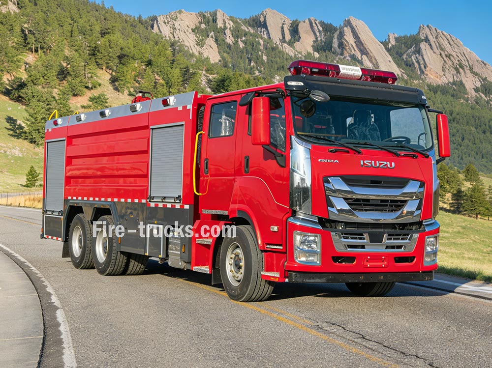
消防車 複数のシステムが連携して機能することで、給水、加圧、消火を実現する。これらの原理を理解することで、消防隊は緊急事態において効果的に活動することができる。 » Ⅰ.消防車の仕組み: ▪ A. ポンプシステム:消火活動の心臓部: 消防車の心臓部はポンプです。この高出力ポンプは、車載タンクまたは消火栓、湖、池などの外部水源から水を汲み上げ、高圧でホースを通して送り出します。最も一般的に使用されているポンプは遠心ポンプで、回転するインペラを利用して水を加圧・送水します。 消防士はポンプパネルにある一連のレバーとゲージを使って水の流れを制御する。必要に応じて圧力を調整し、複数のホースラインに同時に水を送ることができる。 ポンプの種類 特徴 ベストアプリ 単段遠心ポンプ 高流量、中程度の圧力 一般市消防活動 2段式遠心ポンプ 音量と圧力の切り替えが可能 高層ビル、長いホースが横たわっている 多段ポンプ 非常に高い圧力 工業施設、発泡システム ▪ ポンプの主要パラメータ: › 流量:1,200~6,000リットル/分(機種による) › 最大圧力:1.0~2.5 MPa(10~25 bar) › プライミング時間:30秒以下 ▪ B. 貯水槽および貯水システム: › 燃料タンク容量:車両のサイズと種類に応じて、500~1,500ガロン(約2,000~6,000リットル) › タンク材質:耐腐食性ステンレス鋼またはコーティング炭素鋼 › 内部バッフル:緊急対応時の水の動きを制御するための、サージ防止設計の複数の区画 › 充填時間:消火栓または吸水による場合、3分以内 › 水位表示:タンク側面の目視式ゲージ。キャブ内ディスプレイはオプション。 タンクは耐腐食性材料(通常はステンレス鋼またはコーティングされた炭素鋼)で構成されており、緊急走行時の水の噴出を制御する内部バッフルプレートを備えている。 ▪ C. ホースおよびノズルシステム 消防車には、それぞれ異なる機能を持つ様々なホースが搭載されている。 › 攻撃用ホース:直径1.5~2.5インチ ― 火元に直接水を供給します › 給水ホース:直径4~5インチ — 消火栓または他のポンプ車から水を輸送する › ブースターホース:リールに巻かれた小径ホース ― 草火災や車両火災などの小規模な火災に使用 ホースの先端にあるノズルによって、消防士は放水量を制御し、火災の種類に応じて水圧、噴射パターン、方向を調整することができる。 ▪ D. 放水銃 › 放水銃:大規模な消火活動のために大量の水を噴射します。固定�
詳細
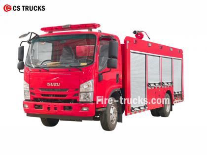
最もプロフェッショナルないすゞ消防車メーカーとして、いすゞNPR水泡消防車のコア設計は、泡消火システムを給水消防車に統合し、水と泡の両方を噴射できる複合消火装置を形成することです。この消防車は単独で消火活動を行うことができ、他の機器に水または泡の混合液を供給することも可能で、乾燥地帯や水不足地域での運用に適しています。 ★ 技術 仕様 CSトラック社の消防車はすべて、顧客の要望に基づいて100%製造されています。 容量 エンジンモデル 水 フォーム 消火ポンプ 消火モニター 2,500L いすゞ4HK1 / 19 0HP 2,500L 500L CB10/40 消防ポンプ PL8/32 2026年公式いすゞ消防車キャブシャーシトラック 2026年製消防車シャーシのオリジナル図面 アイテム いすゞ消防車の設計詳細 デザインコア 水タンク式消防車に泡消火システムを統合し、水と泡の両方を噴射できる二重機能の消防車両を実現しました。主な特徴は以下のとおりです。 ・独立した消火システム ・他の機器への水または泡混合物の供給 ・乾燥地帯や水不足地域に適しており、多機能な使用が可能 全体的なデザインコンセプト 工場や周辺地域での消火ニーズを満たすように設計されており、油、電気、固体物質火災に対する消火能力が強化されています。この車両はシャーシと特殊な車体装備で構成され、信頼性、多機能性、操作の容易さを重視しています。 シャーシの選択 ・実績のある中型または大型のタイプIIシャーシを使用 ・複雑な地形での機動性とトラクションを向上させるため、全輪駆動を推奨します。 2026年型いすゞ700P型新型消防車 コアシステムコンポーネントと設計上の重要ポイント 1. 水タンクと泡消火剤タンク ・材質:ステンレス鋼、耐腐食性 ・推奨容量:水タンク3000~5000L、消火剤タンク300~600L ・構造最適化:内部バッフルにより水室と泡室が分離され、接続ポートを介して単一水タンクモードに切り替えることができ、多目的に使用可能。 2. 発泡剤配合システム ・バランス圧力比例計(コアコンポーネント)を使用して、水と泡消火剤を3%または6%の比率で正確に混合します。 ・流量や圧力の変動に影響されない安定した出力で、専門知識のないオペレーターにも適しています。 ・現場での補充用に外部フォーム吸引口を装備 3. 排出システム ・消火ポンプ:高効率・省エネ型多段遠心ポンプ、流量≧ 4 0 L/S ・放水銃:遠隔操作式水・泡消火兼用放水銃、射程50メートル以上、角度調整可能 ・消防ホースや泡消火ノズル�
詳細
PF5-15 固定式乾燥粉末モニター 乾燥粉末を媒体とし、固定式ベースにより安定した噴霧を実現。化学薬品や倉庫などのエリアに適しており、火災発生初期に燃焼面を素早く覆い、消火効率を向上させます。 その PF5-15固定式乾燥粉末モニター 堅牢な構造で操作が簡単で、自動制御システムと連携して遠隔操作や正確な噴霧が可能です。 » Ⅰ. PF5-15固定式乾燥粉末モニター 構造: PF5-15固定式乾燥粉末モニターの特徴: ● 完全に機能します。 ● シンプルで斬新な構造。 ● 安定したパフォーマンスと簡単なメンテナンス。 ● 入口圧力が低い。 ● 水平・垂直ロック機能付き自動排水バルブを装備。 ● 材質:精密鋳造アルミニウム合金。 ● 砲頭:アルミニウム合金。 » Ⅱ. フォームキャノンPL24 仕様: モデル 流れ ( kg /秒 ) 範囲 ( メートル ) 定格作動圧力 ( Mpa ) ピッチ回転 ( ° ) 水平回転 ( ° ) 長さ×幅×高さ ( んん ) 重さ ( Kg ) PF5-15/40 40 ≥42 0.80 -45 ~ +70 0 ~ 360 980x340x550 28.5 » Ⅲ. 製品用途: PF5-15固定式乾燥粉末モニターを搭載した消防車 PF5-15固定式乾燥粉末モニター試験 PF5-15固定式粉末消火モニターは、長い噴霧距離と広いカバー範囲を特徴とし、迅速に粉末消火バリアを形成できます。化学工場、石油貯蔵所、貯蔵庫などの固定場所に適しており、広範囲にわたって継続的かつ安定した消火能力を提供します。
詳細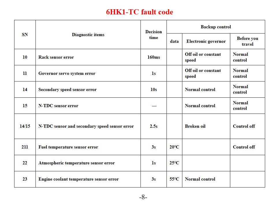
いすゞ 6HK1-TC 消防車 とも呼ばれる いすゞ救助消防車 、エンジン エラー コードの診断と解決策。 いすゞ6HK1-TCエンジンは、先進のTICS燃料噴射ポンプ電子制御システムを採用し、ECU(エンジンコントロールユニット)には自己診断機能が搭載されています。システムが故障を検出すると、「CHECK ENGINE」警告灯が点灯し、対応する故障コードが保存されます。これらのエラーコードの解釈と解決策を理解することで、エンジンメンテナンスの効率を効果的に向上させることができます。 一般的なエラーコードと解決策 Pシリーズのトラブルコード P0101(マスエアフローセンサー回路低) エンジン水温センサーとその配線を点検してください。センサーの電源電圧とアース接続を確認してください。必要に応じてECUまたはセンサーを交換してください。 P0102(マスエアフローセンサー回路高) 燃料の品質とフィルターの状態を確認してください。燃料システムを清掃してください。燃料圧力レギュレーター、燃料ポンプ、インジェクター回路を点検してください。 P0103(マスエアフローセンサーA回路高) センサー信号回路に短絡がないか確認してください。センサーの動作状態をテストし、必要に応じてセンサーまたはECUを交換してください。 デジタルトラブルコード 10(ラックセンサーエラー) ラックセンサーとその配線を点検し、信号伝送が正常であることを確認してください。 11(スピードガバナーサーボシステムエラー) 調速機サーボシステムの動作状態を確認します。関連回路の接続をテストします。 14(補助速度センサーエラー) 補助速度センサーの取り付け位置を確認してください。センサーの信号出力をテストしてください。 15(N-TDCセンサーエラー) N-TDCセンサーの接続を確認する 信号の精度を確認する システムの保守と予防措置 SN 診断項目 決断の時 バックアップ制御 データ 電子ガバナー ご旅行の前に 10 ラックセンサーエラー 160ミリ秒 オイルオフまたは一定速度 通常コントロール 11 ガバナーサーボシステムエラー 1秒 オイルオフまたは一定速度 通常コントロール 14 二次速度センサーエラー 10秒 通常コントロール 通常コントロール 15 N-TDCセンサーエラー — 通常コントロール 通常コントロール 14/15 N-TDCセンサーとセカンダリスピードセンサーのエラー 2.5秒 壊れたオイル コントロールオフ 211 燃料温度センサーエラー 3秒 20℃ コントロールオフ 22 大気温度センサーエラー 1秒 25℃ 23 エンジン冷�
詳細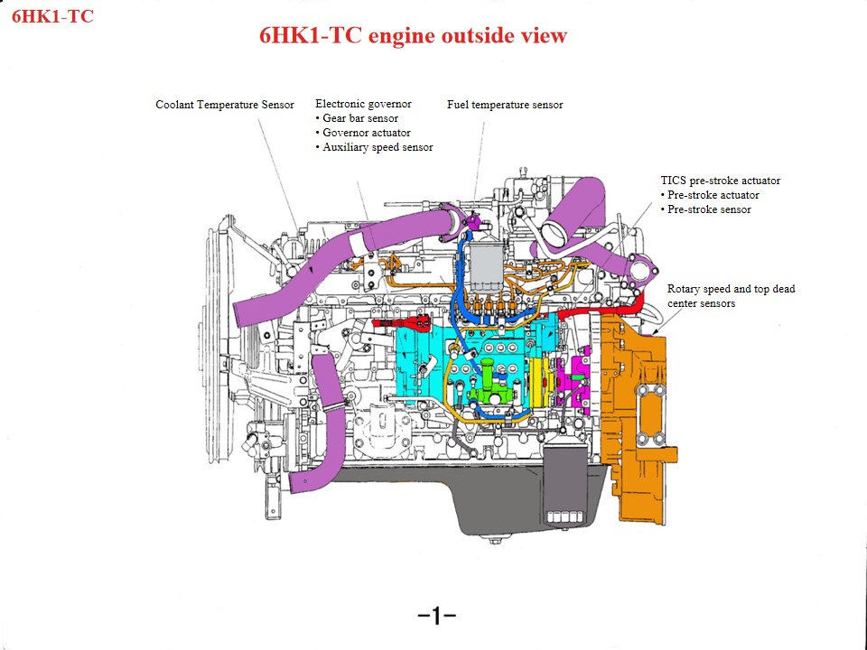
いすゞ 6HK1 消防救助車 別名 いすゞ消防車 、 いすゞ救助消防車のエンジンが過熱した場合は、まず以下の箇所を点検してください 1. 冷却システム: ファンの損傷、ラジエーターの詰まり、サーモスタットの損傷、冷却剤の不足などの問題はすべて、エンジンの過熱の一因となる可能性があります。 2. オイルの品質と量: オイルの品質が悪い場合やオイルが不足している場合も、エンジンが過熱する可能性があります。 3. シリンダーの吹き抜け、シリンダーライナーの亀裂などの機械的な故障もこの現象を引き起こす可能性があります。 重荷重用ディーゼルエンジンであるIsuzu 6HK1エンジンは、メンテナンスにおいて技術仕様を厳守する必要があります。主なポイントは以下のとおりです。 1. 構造理解と分解・組立仕様 クランクシャフト・コネクティングロッド機構 シリンダーライナーはルーズフィット設計のため、分解・組立時に脱落を防ぐには特殊な工具が必要です。標準クリアランスは0.122~0.156mmです ピストン外径は114.894~114.909mmと非常に狭い公差があります。取り付けの際は、ピストンリングの開き方向と「3つのクリアランス」(エンドクリアランス、サイドクリアランス、バッククリアランス)の調整にご注意ください。 下部クランクケースは一体構造のため、変形を防ぐためメンテナンス時には吊り上げる必要があります。 タイミングシステムのアライメント ギアボックスの組み立て中は、クランクシャフトギアとアイドラーギアのマークを合わせます。カムシャフトのBマークはシリンダーヘッドの表面と面一でなければなりません。エンジンは第1シリンダーの圧縮上死点にある必要があります 燃料噴射ポンプを取り付けるときは、タイミング ポインターをコネクタの S ポイントに合わせ、噴射アドバンス マークをポンプ本体のポインターに合わせます。 • リニアDCモーターは、制御ユニットの出力信号に基づいてコイルを上下に動かします • コイルアセンブリに設置されたコネクティングロッドは、コイルの上下運動をコネクティングブロックに伝達し、コネクティングブロックはラックの端に設置されています。コネクティングブロックの押圧により、ラックは左右に移動し、燃料噴射量を変化させます。コイルアセンブリが上昇すると、リンクがラックを押してオイル量を増加させます。逆に、コイルアセンブリが下降すると、ラックはオイル量を減少させる方向に移動します。コラムの機能
詳細
読み進めて、最新情報を入手し、購読して、ご意見をお聞かせください。


 日本語
日本語 English
 français
 Deutsch
 русский
 italiano
 español
 português
 Nederlands
 العربية
 한국의
한국의 Türkçe
 Melayu
 ไทย
ไทย Tiếng Việt
 Indonesia
  中文
中文 қазақ
қазақ Filipino
 မြန်မာ
 српски


 IPv6ネットワークがサポートされています